Diesel Injecter Repair
When it comes to removing and installing fuel injector sleeves in Diesel engines, Hillide Machine has the wide range of tools, sleeves and support equipment to do the job efficiently and porperly Irontite Diesel Fuel Injection Repair System.
Phone:1-781-321-9625
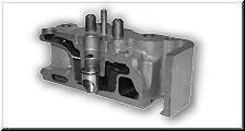
Cummins Diesel Injector Tube Installation.
Injectors
The fuel injector, or what is often referred to as a unit injector is used by Detroit diesel in all series of engine that they build. Certainly, there are some variations in basic design and in the actual testing procedures used; however, the function and operation is the same for all.
Unit injectors were designed with simplicity in mind both from a control and adjustment outlook. They are used on direct-injection, open-type, two-cycle combustion chamber engines manufactured by General Motors. No high-pressure fuel lines or air-fuel mixing or vaporizing devices are required with these injectors.
The fuel from the fuel pump is delivered to the inlet fuel manifold (cast internally within the cylinder head) at a pressure of 65 to 75 psi. The fuel then flows to the injectors through fuel pipes called jumper lines. Once the fuel from the pump reaches the injector, it performs the following functions:
1. Times injection: liming of the injector is accomplished by movement of the injector control rack, which causes rotation of the plunger within the injector bushing. Since the plunger is manufactured with a helical chamber area, this rotation will either advance or retard closing of the ports in the injector bushing, and therefore the start and end of the actual injection period. Pushrod adjustment establishes the height of the injector follower above the body. In turn, this factor establishes the point or time that the descending plunger closes the bushing ports, allowing injection to begin.
2.Meter the fuel: The rotation of the plunger by movement of the injector control rack will advance or retard the start and end of injection. If the length of time that the fuel can be injected is varied, the amount of fuel will be varied.
3.Pressurizes the fuel: Fuel that is trapped underneath the plunger on its downward stroke will develop enough pressure to force its way past the check valve or needle valve, therefore entering the combustion chamber.
4.Atomizes the fuel: Fuel under pressure that forces its way past the check or needle valve must than pass through small holes or orifices in the injector spray tip. This passage breaks the fuel down into a finely atomized spray, as it enters the combustion chamber.
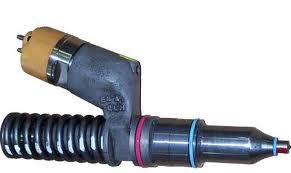
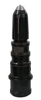
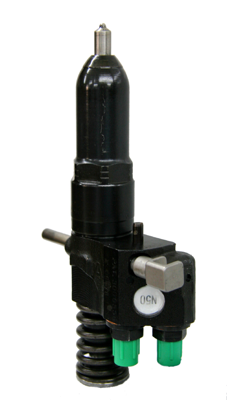
The two-stroke Detroit diesel engine unit fuel injector is located in the cylinder head. The injector sits in a copper tube in the head that is surrounded by water for cooling purposes. The injector is placed in the cylinder head by a dowel pin on the underside of its body. The injector is held in place by a single bolt and clamp arrangement. The clamp sits low on the injector body, which allows clearance for the valve bridge operating mechanism. The injector is also known as an offset body because the fuel inlet and outlet are offset to one another. This arrangement allows sufficient clearance between the valves.
Each injector has a circular disc pressed into a recess at the front side of the injector for identification purposes. The identification tag indicates the nominal output of the injector in cubic millimeters. Both the plunger and bushing are marked with corresponding numbers to identify them as mating parts. Therefore, if either the plunger or bushing requires replacement, both must be replaced as an assembly.
The injector control rack for each injector is actuated by a lever on the injector control tube that, in turn, is connected to the governor by mean of a fuel rod. hese levers can be adjusted, thus permitting a uniform setting of all injector racks. Basic operation of the unit injector is as follows:
•Fuel, under pressure, enters the injector at the inlet side through a filter cap and filter element. rom the filter element, the fuel passes through a drilled passage into the supply chamber—that area between the plunger bushing and the spill deflector and the area underneath the injector plunger within the bushing. The plunger operates up and down in the bushing, the bore of which is open to the fuel supply in the annular chamber by two funnel-shaped ports in the plunger bushing.
•The plunger descends, under pressure of the injector rocker arm, first closing of the lower port and then the upper. Before the upper port is shut off, fuel being displaced by the descending plunger flows up through the "T" drilled hole in the plunger and escapes through the upper port and into the supply chamber.
•With the upper and lower ports closed off, the remaining fuel is subjected to increased pressure by the continued downward movement of the plunger. When sufficient pressure is built up, it opens the flat, non-return, check valve. The fuel is compressed until the pressure force acting on the needle valve is sufficient to open the valve against the downward force of the valve spring. As soon as the needle valve lifts off its seat, the fuel is forced through the small orifices in the spray tip and atomized into the combustion chamber.
•As the plunger continues to descend, it uncovers the lower port, so fuel pressure is relieved, and the valve spring closes the needle valve, ending injection. Then the plunger returns to its original position and waits for the next injection cycle.